Sign In

Publication
DIFFUSERS
section 2 SEPT 2005
PART G
R
Air Valves
supply and exhaust
ventilation systems
supply and extract valves
type finish
KE / White (SEE) / 160 / 3
quantity
EXAMPLE :
size
d + 7
50
D
d (o/s)
DIMENSIONS (mm)
Size D d
100 130 98
125 155 123
150 178 148
160 190 158
200 236 198
introduction
fixings
finishes
The K series range of small format
supply and extract air terminals
are ideally suited for low air volume
applications such as domestic
residences or hotel rooms.
The range comprises a supply valve
(type KE), two styles of extract valve
(types KK and KS) and an extract fire
damper (type KF).
All models have an aerodynamically
profiled, adjustable and lockable
centre cone which is designed to
provide an easy method of flow
regulation, with minimal influence on
the noise level.
Gloss white epoxy stove enamelled paint is offered as a standard finish to
provide maximum corrosion resistance in damp environments. A full range
of colours are however available in either the BS or RAL ranges. See Part I
for details.
The valves are supplied with an easy fit bayonet collar which can either be
rivetted to the duct or screw fixed to the mounting surface.
ordering
details
mounting
collar
type K
Supply and Extract Valves
DESIGN FEATURES
2
Dia D
H Max
Dia d
6
Datum
+
_
6
+
_
Dia D
H
Dia d
Datum
Dia D
Dia d
H
Datum
6
+
_
Dia d
Dia D
Datum
6
+
_
Mounting Collar
Fusible Link closes
centre cone at a
temperature of 74oC
DIMENSIONS (mm)
Size D d H
KE100 137 94 47
KE125 161 110 49
KE150 202 135 60
KE160 212 145 60
KE200 249 194 75
DIMENSIONS (mm)
Size D d H
KK100 137 75 70
KK125 161 100 85
KK150 202 120 85
KK160 212 130 85
KK200 249 157 110
DIMENSIONS (mm)
Size D d H
KS100 134 87 91
KS125 160 108 97
KS150 191 130 85
KS160 191 130 85
KS200 241 177 104
DIMENSIONS (mm)
Size D d
KF100 140 99
KF125 165 124
KF160 200 159
KF200 250 199
Supply and Extract Valves
DIMENSIONS
design features
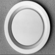
TYPE KE
Supply air valve
TYPE KK
Extract air valve
TYPE KS
Low Noise Extract
air valve
TYPE KF
Extract Fire
Damper
R
3
AIR FLOW RATE (l/s)
SIZE PARAMETER
CONE POSITION
PRESSURE FACTOR
10 15 20 25 30 40 50 60 70 80 90 -6mm +6mm
KE80
KE100
KE125
KE150
KE160
KE200
THROW (m)
PRESSURE LOSS (Pa)
NR LEVEL
THROW (m)
PRESSURE LOSS (Pa)
NR LEVEL
THROW (m)
PRESSURE LOSS (Pa)
NR LEVEL
THROW (m)
PRESSURE LOSS (Pa)
NR LEVEL
THROW (m)
PRESSURE LOSS (Pa)
NR LEVEL
THROW (m)
PRESSURE LOSS (Pa)
NR LEVEL
1.0 1.5 1.9 2.2
25 55 95 140
15 23 30 35
9.0 0.4
0.7 1.1 1.6 1.9 2.2 2.7
12 25 40 58 90 150
20 25 35 42
3.3 0.4
1.1 1.5 1.9 2.1 2.6 3.1 3.4 3.6
12 20 30 55 85 120 170
20 25 30 35
3.3 0.5
0.6 0.9 1.2 1.6 1.9 2.2 2.5 2.7
10 15 22 40 70 90 130 180
17 25 32 35 42
2.2 0.4
0.6 0.8 1.0 1.2 1.6 1.8 1.9 2.1 2.3
12 17 25 38 60 85 105 140 200
15 23 30 33 37 43
2.9 0.4
0.6 0.9 1.2 1.6 1.9 2.2 2.5 2.7
10 15 22 40 70 90 130 180
17 25 32 35 42
2.2 0.4
SIZE PARAMETER
KK80
KK100
KK125
KK150
KK160
KE200
KK200
AIR FLOW RATE (l/s) CONE POSITION
PRESSURE FACTOR
10 15 20 25 30 40 50 60 70 80 90 -6mm +6mm
PRESSURE LOSS (Pa)
NR LEVEL 1.9 0.6
22 50 82 140
15 23 30
1.4 0.6
15 32 60 90 120 200
15 21 24 30
PRESSURE LOSS (Pa)
NR LEVEL
1.5
18 31 48 70 120 180
15 21 30
PRESSURE LOSS (Pa)
NR LEVEL
1.4
17 34 42 70 110 170
17 24 30
PRESSURE LOSS (Pa)
NR LEVEL
1.4
17 34 42 70 110 170
17 24 30
PRESSURE LOSS (Pa)
NR LEVEL
1.5 0.65
50 75 100 140 170
22 27 30 35
PRESSURE LOSS (Pa)
NR LEVEL
The following data is all based on an optimum centre cone position 6mm
below the level of the outer frame. Where applicable, correction factors may
be applied for other cone settings.
Jet throws are given in meters to a terminal velocity of 0.2m/s.
Noise data is expressed in terms of NR level with a room absorption factor
of 8db.
basis of
data
noise levels
throws
PERFORMANCE DATA
Supply and Extract
For more information on supply and extract valves talk to Brooke Air Sales
Enquire Now
List your company on FindTheNeedle.