Sign In


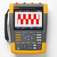
The Fluke MDA 550 Series III Motor-Drive Analyser saves time and eliminates the hassle of setting up complex measurements, while simplifying motor-drive troubleshooting.
Simply select a test and the step-by-step guided measurements show you where to make voltage and current connections, while the preset measurement profiles ensure you will capture all the data you need for each critical motor-drive section-from the input to the output, the DC bus, and the motor itself. From basic to advanced measurements, the MDA-550 has you covered, and with a built-in report generator you can quickly and easily generate as-found, and as-left reports with confidence.
The MDA-550 is the ideal portable motor-drive analysis test tool and can help safely locate and troubleshoot typical problems on inverter type motor-drive systems.
FEATURES
Guided testing with graphical step-by-step connection diagrams.
Preset measurement profiles reduce setup complexity.
Built-in report writing capabilities.
Easily produce as-found and as-left troubleshooting reports.
INCLUDED ACCESSORIES
1x BP 291 li-ion battery pack, 1x BC190 charger/power adapter, 3x VPS421 100:1 high voltage probes with alligator clips, 1x VPS410-II-R 10:1 500MHz voltage probe, 3x i400s ac current clamp, 1x SVS-500 shaft voltage set (3x brush, probe holder, two-piece extension rod and magnetic base), large size, protective carrying case with rollers (C437-II), FlukeView-2 PC software (full version) and WiFi dongle.
Fluke MDA-550 Series III Motor Drive Analyser Specifications
Measurement Function
Specification
DC voltage (V DC)
Maximum voltage with 10:1 or 100:1 probe
1000 V.
Maximum resolution with 10:1 or 100:1 probe (voltage to ground)
1mV / 10mV.
Full scale reading
999 counts.
Accuracy at 4 s to 10 us/div
+ (1.5 % + 6 counts).
True-rms voltage (V ac or V ac + dc) (with DC coupling selected)
Maximum voltage with 10:1 or 100:1 probe (voltage to ground)
1000 V.
Maximum resolution with 10:1 or 100:1 probe
1 mv / 10 mV.
Full scale reading
999 counts.
DC to 60 Hz
+ (1.5 % + 10 counts).
60 Hz to 20 kHz
+ (2.5 % + 15 counts).
20 kHz to 1 MHz
+ (5 % + 20 counts).
1 MHz to 25 MHz
+ (10 % + 20 counts).
PWM voltage (V pwm)
Purpose
To measure on pulse width modulated signals, like motor drive inverter outputs.
Principle
Readings show the effective voltage based on the average value of samples over a whole number of periods of the fundamental frequency.
Accuracy
As Vac+dc for sinewave signals.
Peak voltage (V peak)
Modes
Max peak, min peak, or pk-to-pk.
Maximum voltage with 10:1 or 100:1 probe (voltage to ground)
1000 V.
Maximum resolution with 10:1 or 100:1 probe
10 mV.
Accuracy
Max peak, min peak
+ 0.2 division.
Pk-to-pk
+ 0.4 division.
Full scale reading
800 counts.
Current (AMP) with current clamp
Ranges
Same as V ac, Vac+dc or V peak.
Scale Factors
0.1 mV/A, 1 mV/A, 10 mV/A, 20 mV/A, 50mV/A, 100 mV/A, 200 mV/A, 400 mV/A.
Accuracy
Same as Vac, Vac+dc or V peak (add current clamp accuracy).
Frequency (Hz)
Range
1.000 Hz to 500 MHz.
Full scale reading
9999 counts.
Accuracy
+ (0.5 % + 2 counts).
Voltage/Herz ratio (V/Hz)
Purpose
To show the measured V PWM value (see V PWM) divided by the fundamental frequency on vari- able ac motor speed drives.
Accuracy
% Vrms + % Hz.
Voltage unbalance drive input
Purpose
To show the highest percentage difference of one of the phase vs average of the 3 true-rms voltages.
Accuracy
Indicative percentage based on Vac+dc values.
Voltage unbalance drive output and motor input
Purpose
To show the highest percentage difference of one of the phase vs average of the 3 PWM voltages.
Accuracy
Indicative percentage based on V PWM values.
Current unbalance drive input
Purpose
To show the highest percentage difference of one of the phase vs average of the 3 AC current values.
Accuracy
Indicative percentage based on Aac+dc values.
Current unbalance drive output and motor input
Purpose
To show the highest percentage difference of one of the phase vs average of the 3 AC current values.
Accuracy
Indicative percentage based on A ac values.
Rise and fall time
Readings
Voltage difference (dV), time difference (dt), voltage vs time difference (dV/dt), overshoot.
Accuracy
As oscilloscope accuracy.
Harmonics and spectrum
Harmonics
DC to 51st.
Spectrum ranges
1.9 kHz, 9-150 kHz (20 MHz filter on), up to 500 MHz (voltage modulation).
Shaft voltage
Events / second
Indicative percentage based on rise and fall time (Impulse discharges) measurements.
Report data capture
Number of screens
Typical 50 screens can be saved in reports (depends on compression ratio).
Transfer to PC
Using 32 GB or smaller 2 GB USB stick or mini-USB to USB cable or WiFi link and FlukeView™ 2 for ScopeMeter®.
Probe settings
Voltage Probe
1:1, 10:1, 100:1, 1000:1, 20:1, 200:1.
Current Clamp
0.1 mV/A, 1 mV/A, 10 mV/A, 20 mV/A, 50 mV/A, 100 mV/A, 200 mV/A, 400 mV/A.
Shaft Voltage Probe
1:1, 10:1, 100:1.
Safety
General
IEC 61010-1: Pollution Degree 2.
Measurement
Measurement IEC 61010-2-030: CAT IV 600 V / CAT III 1000 V.
Maximum voltage between any Terminal and Earth Ground
1000 V.
Max. input voltages
Via VPS410-II or VPS421 1000 V CAT III / 600 V CAT IV.
BNC Input
A, B, C, D directly 300 V CAT IV.
Max. Floating Voltage, test tool or test tool with VPS410-II / VPS421 voltage probe
From any terminal to earth ground 1000 V CAT III / 600 V CAT IV Between any terminal 1000 V CAT III / 600 V CAT IV.
Working voltage between probe tip and probe reference lead
VPS410-II: 1000 V
VPS421: 2000 V.
For more information on Fluke MDA-550 Series III Motor Drive Analyser talk to Cuthbertson Laird Group
Enquire Now
List your company on FindTheNeedle.