 Add My Company
Sign In

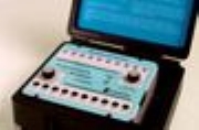
PMC Signal Tester aids in the process of diagnosing I/O and wiring
problems in the vehicle. The tester may be connected at any point
around the vehicle where there is access to the 3 wire communications
bus. The connection may be made while the vehicle's multiplex
system is operating, without detrimental effect.
When connected, the tester is capable of displaying the status of
every input and output in the system, or forcing any input or output in
the system on.
The tester has 10 push button switches and 10 LED's, each of which
are related to a channel. Two, 16-position rotary switches are
used to set the switches and lights to any module address.
The switches can be set for one module address and the
lights can be set for another, or the switches and lights
may be set for the same address. If a push button
on the tester is set to an output channel's
address, pushing the button will cause the
output to turn on. The LEDs will light to
reflect the status of both inputs and outputs.
Since it is acceptable to have more than one
module in the PMC system with the same
address, the tester can be set to duplicate any
module from Athrough P.
To use the tester, the technician will attach the tester to
the 3 wire bus via the cable set provided. The rotary switches are then
set to the address of the modules being simulated. If a channel is active
(Output is on, or Input is on) the associated channel LED will illuminate. If a channel is an input channel and the
associated push button is pressed, the PMC system will respond as though the actual input switch is active. If the
channel is an output channel, pressing the associated button will force the system to turn the channel on regardless
of the boolean written for the channel, in which case the load associated with the channel should turn on. If it
doesn't, a simple test using a test light can be used to check the output and wiring from the output module to the
load. This allows the tester to be used to test the functionality of every module and every input, or output in the
system.
The PMC signal indicator light indicates that communication with the CPU and the tester is working. This tests the
functionality of theCPUand the 3 wire communications bus.
The test set is provided in an 8.5 X7.8 X3.75 inch plastic box with hinged lid.
For more information on PMC Signal Tester talk to Intellitec MV Ltd
Enquire Now
List your company on FindTheNeedle.
