 Add My Company

How do we convert and protect raw signals from industrial environments?
Measurement and control of physical properties are the foundation of all critical industrial technologies. Here Ian Loudon, international sales and marketing manager at remote monitoring specialist Omniflex, explains the challenges of industrial signal conditioning (SC) and the importance of safety engineering.
Automation for industry 4.0, process control, data acquisition and alarm processing all rely on the conversion of physical signals to a standardised, usable format, that engineered systems can reliably use to manage industrial processes.
At its simplest, signal conditioning is the process by which physical properties such as temperature, humidity, pressure, vibration, frequency, presence or absence, relay logic, and flow are converted by transducers into usable electrical signals, suitable for measurement and control systems. Any electronic device that detects and quantifies a physical property like this is referred to in industry as a transducer.
Transducers must be close to the measurement point, in a harsh and possibly dangerous environment, to convert a physical property into an engineering signal for measurement and control. The bigger the measured process, the more signals need to be measured and often the farther away the supervisory and control systems.
We can think of signal conditioning as an interface between the plant and the field. Control and monitoring systems are sensitive and need to be protected from harsh environments. Voltage spikes, high temperatures and electrical noise are all potentially damaging, and signal conditioning provides protection to mitigate these harsh field conditions, typically using electrical isolation (galvanic or optical), noise immunity and surge protection mechanisms.
Field devices or transducers on a process are normally wired back individually from the process to marshalling panels, where consolidation and protection of these signals can be managed in the field. From there, multiple signals are run together in multi core cables to control systems.
A signal conditioner on a marshalling panel receives and converts the transducer input from the field, for example a temperature value. There, the signal conditioning system again converts the signal to the industry standard range of 4-20 mA and transmits it to the control system.
4-20 mA is used for a number of reasons. 4 mA = 0 per cent, minimum value, and 20 mA = 100 per cent or maximum value. This can be interpreted by the measurement and control system and expressed in SI units. The signal conditioner also allows the field signal to be amplified and zoom in on a portion of the transducer’s range.
A good example of this is a thermocouple, a temperature transducer that measures a wide range of temperature, such as -100°C to 1,280°C. The signal conditioner allows scaling and selection of the portion of the range that control is interested in.
This standard exists because a voltage output would result in a volt drop on the cable, introducing an error in measurement, whereas the current output over a long distance can be actively compensated in the system circuitry with voltage manipulation. Additionally, using four mA as a ‘live zero’ makes it very easy to detect a system fault, for example a cable break, as the current will fall to true zero.
Challenges of signal conditioning
Electromagnetic interference (EMI) is one of the biggest challenges involved with signal conditioning in industrial environments: any factors that jeopardise the accurate transmission of signals to the control system must be dealt with. To resolve this, the signal conditioning system is electrically isolated from the plant at an industry standard of 1,500 VAC, meaning this is the maximum difference between input and output that the signal conditioner can handle without breaking down.
Signal amplification and attenuation are also issues that require attention. If signals have to travel long distances, tens or even hundreds of metres, they can attenuate because of wire resistance, meaning an inaccurate signal reaches the control system. Similarly, amplification of low-level voltage signals is complex, as any interference or non-linearities can be amplified along with the desired signal.
All of these challenges are mitigated by the 4-20 mA current range. Current signals naturally withstand EMI better than voltage signals, particularly over long distances. Other control devices can share the current loop as part of the control system.
Safety in signal conditioning
Signal conditioning units adhere to IEC 61508 and so must meet safety integrity level (SIL) risk reduction requirements. This requires careful design, especially considering the hazardous industrial environments through which these electronic signals travel. The surge protection components must prevent the energy involved from igniting anything flammable or causing an explosion in a natural gas processing plant, for example.
Furthermore, the failure of a signal conditioner must not expose the sensitive control system to the aforementioned environmental threats. A reputable manufacturer, such as Omniflex, will employ fail to safe, redundancy and automatic shutdown functions to ensure that signal conditioning failure does not lead to system damage.
Signal conditioning is an essential mechanism for industrial plants to collect information about, and monitor, their processes, and only through precise design can plant engineers ensure reliable incoming data flow. Technical issues like signal attenuation, EMI and process safety are all important to consider, but industry standard ranges for signal current and electrical isolation keep things running smoothly.
What to do next
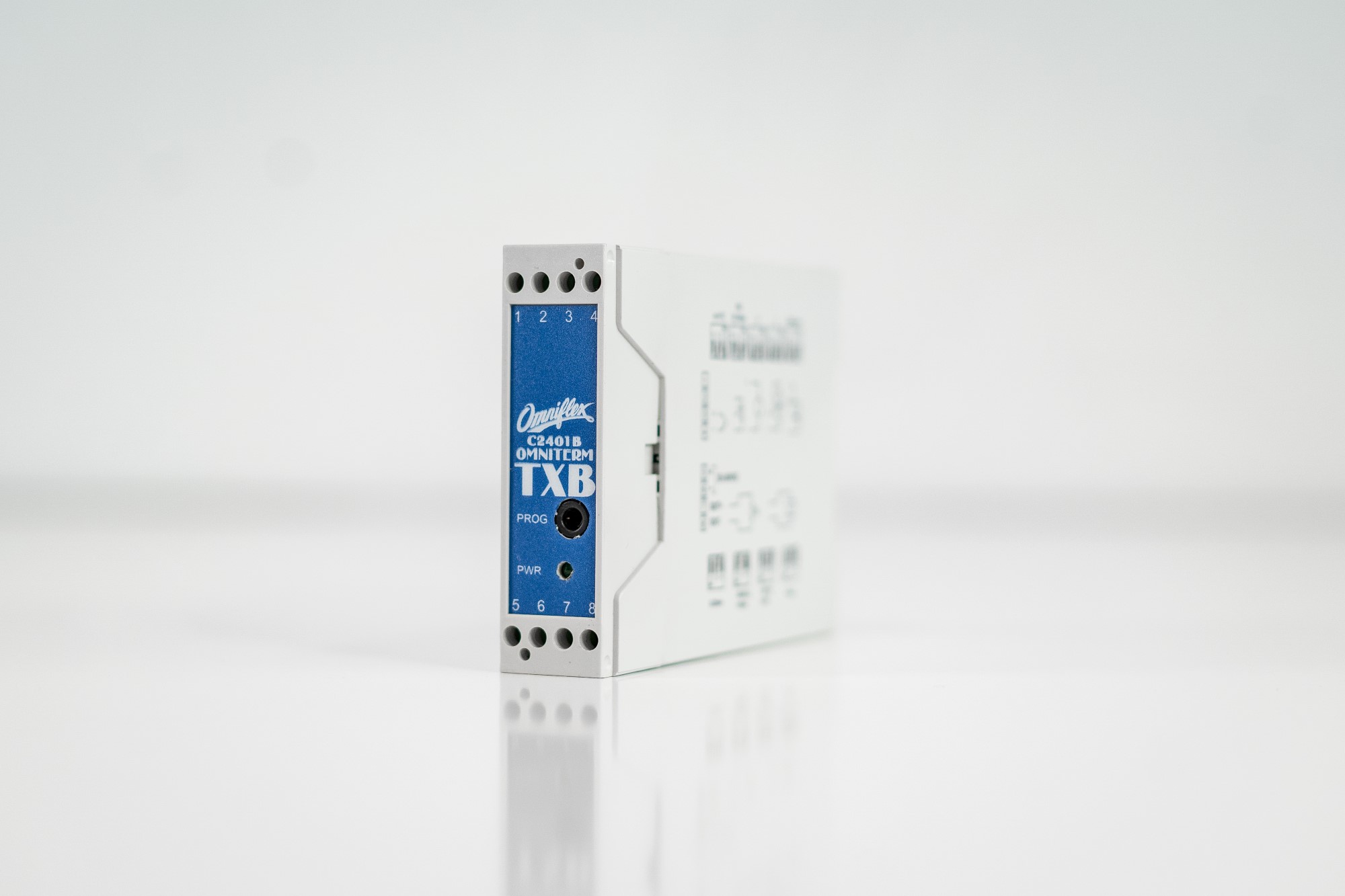
To find out how Omniflex’s COTS (Commercial off the Shelf) signal conditioning unit, the Omniterm TXB, can help you avoid costly problems in industrial process monitoring, read the product brief on our website
For more information on Signal conditioning is the protective armour between plant and field talk to Omniflex UK Limited

