 Add My Company
Sign In

The purpose of this article is to demonstrate that if there is a requirement to lower plant emission rates in-line with government compliance, avoiding an inspection and advice from a specialist, may only lead to insufficient results and additional cost to achieve it.
Further to this, the article also intends to demonstrate the differences in operation and collection efficiencies between a MFTR (Mid-Frequency Transformer Rectifier controller/set) and the HFTR (High-Frequency Transformer Rectifier controller/set).
Schenck Process received an order to replace a conventional TR Set (Transformer Rectifier
Set) with a High Frequency TR Set on a client’s cement plant, (unit-8), in Rajasthan, India.
Prior to contacting Schenck Process, the client had installed 1 x MFTR, with the intention to lower their emission rates, however the result was not sufficient.
Figure 1: Side view of three fields ES
The plant facility had a capacity of 3000 TPD (tons per day) and utilised three field Electrostatic Precipitators on each of their clinker coolers, to control emissions. The clinker coolers were originally equipped with Him-Enviro Electrostatic Precipitator (ESP) and powered by conventional TR Sets, operating at 50 Hz.
The ESP was originally designed for a gas flow rate of 126.94 m³/s, with a maximum inlet dust concentration of 40 g/Nm3 and outlet emission of <50 mg/Nm³ when all fields were in operation. However prior to the modifications, the plant could only reach an outlet emission of 87mg/Nm³.
To counteract this, the customer had installed 1 x MFTR controller on Unit-3, operating at 200Hz, onto the existing inlet TR Set to increase the average operating voltage of the ESP.
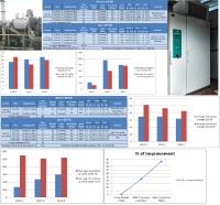
Figure 2 below, shows the emission measurements and operating parameters of the Unit-3 Cooler ESP before and after the MFTR installation.
Figure 3 and 4, graph the kV (Kilovolts to volts) and mA (mill amperes into watts/volt) before and after the MFTR was installed. There is only a minor change in both secondary voltage (kV) and the (mA) compared to when only conventional TR sets were in operation. There is slight improvement in the Secondary voltage on the on the 1st field, but the 2nd and 3rd fields don’t have any improvement. Figure 2 also shows the change in the ESP performance. Overall, there is a 22% PM (particulate matter) reduction, but the emissions are still over the required maximum limit.
As a result, the customer contacted Schenck Process to discuss potential solutions to meet the government emission regulations. Schenck Process was able to utilise their process expertise to provide the customer with performance estimates for a variety of scenarios. The confidence generated by this analysis prompted the customer to quickly adopt a proposed solution.
Schenck Process provided a complete solution, which included an ESP inspection and rectification services bundled with a 1 x 60kw/67KV/900mA HFTR. The new power supply was commissioned at the plant’s Unit 8 clinker cooler ESP.
After the HFTR installation, the outlet PM emission achieved 42mg/Nm3, well below the original 80mg/Nm3 and within the government limits. The ESP performance improvement was 47.2% with 1 x HFTR installed. (See Figure 6)
The HFTR was able to achieve these results by supplying a more constant voltage to the ESP, in comparison to the original conventional TR sets or MFTR. This eliminated unwanted peaks in the output voltage waveform that caused excess sparking and poor performance. With a more constant output voltage, the HFTR was able to introduce extra current into the ESP for better charging, which led to improved collection efficiency and lower PM emissions.
Figure 7 and 8 show the secondary kV & mA before and after the HFTR was installed. The HFTR increased the secondary voltage (kV) and secondary current (mA) drastically in the 1st field. The HFTR performance impacted the 2nd and 3rd field as well, as there is improvement in the kV & mA of the existing single phase 50Hz conventional TR Sets. As per the data in Figure 6 this led to overall higher collection efficiency to reduce the emissions. The emissions were therefore reduced from an average of 80mg/Nm3 to an average of 42 mg/Nm3 only with 1 HFTR installed on the Unit-8 cooler ESP. The overall performance of the HFTR 1st field is thus 47.2%.
In Summary the MFTR controller could only operate at 200HZ and required 50% de-rate of the original conventional TR Set. There were higher losses when operating at the original 50 Hz at mid frequency, therefore higher power was consumed, when compared to HFTR, which is designed to operate at a high frequency.
The MFTR used series resonance, which required a new CLR (??) so that the mid frequency inverter could vary output voltage through modulation. This caused higher stress on the inverter. The MFTR operated using soft switching, which waits for zero crossing condition to operate the insulated-gate bipolar transistor (IGBT).
Following the above performance tests, the HFTR Set showed a greater improvement in the performance of the ESP when compared to the MFTR set. As shown in Figure 9 there was a 47.2% improvement for the HFTR vs a 22% improvement for the MFTR. These results were attributed to an increase in secondary voltage and current into the ESP, due to more constant secondary voltage. Overall, a more efficient solution enabled a customer to finally meet their process requirements.
For more information on Schenck Process ESP Solutions Enable Emission Compliance in Cement Plant Application talk to Schenck Process UK Ltd
Enquire Now
More News
List your company on FindTheNeedle.

